Challenge
The core noise, IO noise, digital circuit noise, and PLL noise should be characterized before making high-volume production. Power noise measurement results are functions of power noise frequency, system circuit sensitivity, and input patterns.
As the system package gets smaller, such as package-on-package or multi-chip packages, the power noise becomes more important.
Power Noise Measurement Tips
- System power noise should be set up to include different state transitions, such as reset, sleep/wakeup mode, read/write turn-around, and multiple IO switching mode.
- In additional to random noise, the data bus frequency should include power plane resonance frequency patterns that are usually about hundreds of megahertz.
- Use a bypass cap close to the ASIC on the backside of the board for power noise probing.
- The probe should have short ground leads to reduce the probing effect.
- Avoid ground lead since it may create AC voltage drop that can be included in the noise source, especially for high frequency power noise measurements.
Helpful links
- Power Integrity course by CEI
- Designing and modeling of PI
- Signal/Power integrity interactions
Good Practices
Power plane impedance measurement, including silicon, package, bypass capacitors, PCB and VRM, can affect power plane noise resonance frequency.
- A significant noise source can be observed if the system is excited close to the system resonance frequency.
- In order to measure power plane impedance, use a strong probe tips to probe the bypass capacitors.
Power Integrity Probing Demonstrations

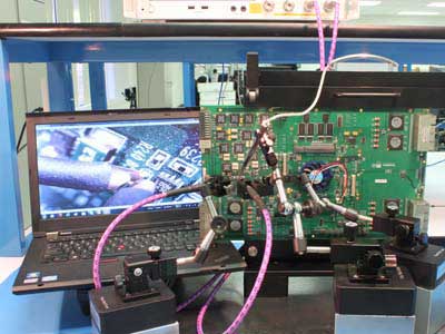
Power Integrity probing displayed on a PC

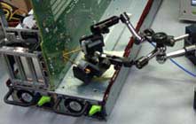
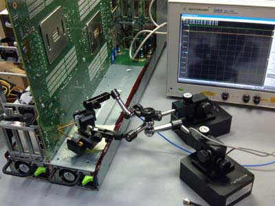
Power Integrity probing with FP160 and RProbe


