Challenge
How do you know the impedance measured by PCB fab house is correct? Accurate TDR probing requires calibration substrate to remove the errors from cable, connectors and probes. Engineers should consider TDR calibration standard to calibrate TDR measurement setup.
TDP Probing Tips
- The most common mistake for impedance measurements is trying to meet the spec of ohm but ignore the edge-rate setting on the TDR. A faster edge rate may not be seen by the real signal on the PCB.
- Short trace must be measured with fast edge rate in order to resolve the impedance. Most of the high-end TDR machine from Tek or Agilent has the sampling head as a separate unit from the main frame. However, the ringing at the probing point can last more than a hundred picosecond, which prevents the short trace measurement.
- Agilent 54754A TDR can be calibrated at the TDR probe tip so that the ringing of the probe contact can be minimized.
- Another solution is to use high bandwidth vector network analyzer (VNA) to extract the S11 or SDD11. Then, change the s-parameter into timing domain. Since Vector Network Analyzer allows calibration at the probe tips, the ringing at the probe tips is reduced significantly.
Helpful Links
Good Practices
- A fab house typically verify the impedance by measuring a coupon on the edge of the PCB. The difference between the signal traces and the coupon can be more than 3-5 ohm, depending on the PCB layers.
- This error may be significant for the validation of high-volume production because the nominal impedance distribution may be less than 3-5 ohm.
- It is helpful to ask your fab house use the same TDR calibration substrate.
TDR Demonstrations

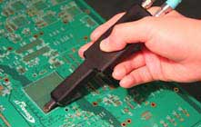
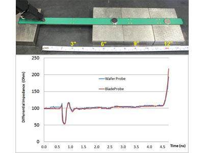
TDR probing with BladeProbe and TDR coupon

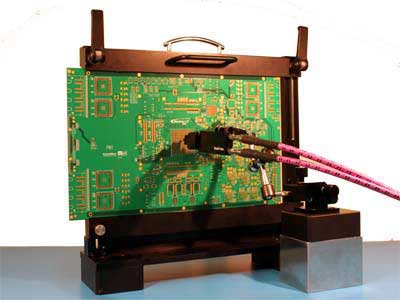
Vertical TDR probing


